How to Build a PLC Motor Control Panel
How to Build a PLC Motor Control Panel. In this Article i will show you how to build and Program a PLC Motor Control Panel From scratch.
The Function of this Motor Control Panel should be as below
- Able to rotate Forward Direction
- Able to rotate Reverse Direction
Forward Direction Connection
| No | Motor Phase | 3Phase |
|---|---|---|
| 1 | U | Phase 1 |
| 2 | V | Phase 2 |
| 3 | W | Phase 3 |
Reverse Direction Connection
| No | Motor Phase | 3Phase |
|---|---|---|
| 1 | U | Phase 1 |
| 2 | V | Phase 3 |
| 3 | W | Phase 2 |
Create an IO List
In this Project the IO List is as below
1) Digital Input -> Emergency Stop , Motor On / Off Switch , Motor Forward Switch , Motor Reverse Switch. Total 4 Digital Input
2) Digital Output -> Motor On Contactor , Motor forward Contactor , Motor Reverse Contactor. Total 3 Digital Output
Create Bill Of Material List
In this Project the Bill of Material List is as below
- Motor On Contactor 3 Pole
- Overload Protection 3 Pole / or Fuse
- Motor Forward Contactor
- Motor Reverse Contactor
- PLC with enough DI and Input
- Bus Bar for AC
- Terminal Blocks
- AC Phase Indicator
- Motor On Indicator
- Motor Forward Indicator
- Motor Reverse Indicator
- Emergency Switch
- Motor On Switch ( Momentary)
- Motor Forward Switch ( Momentary)
- Motor Reverse Switch
- Electrical Panel
- 24VDc Power Supply
- Bus Bar for 24 VDC
- Control Cable
- AC Cable
- Grounding Bar
- Grounding Cable
- Trunking
- Knife edge Fuse for PLC Isolation
- Alarm Indicator if any
Create Mechanical and Electrical Drawing
Get all the Dimension of the listed material above from Vendors Website and create the Electrical Panel Drawing. I assume you know how to do that and i will not elaborate on that much.
Create the Electrical drawing.
Write the PLC Logic
As for this Project the PLC Logic is as Below
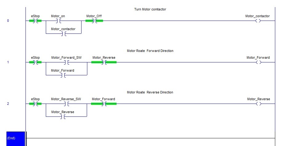 Explanation of the PLC Logic
If you Write the PLC logic , please make sure that you assign an ” Understandable ” and Meaningful Tag . So in future if other Engineer Trouble shoots your Panel. They have an Idea on how to read your program.
Be open !! put some comments in your Logic.
I have encounter some difficult moment trouble shooting programs which does not have any comments at all. Be a Responsible Engineer
- The “0” Rung is logic is to Turn on the Motor Contactor
- In plain English -> when the Emergency Stop is not activated and Motor is not Off and the User press the Momentary Switch ” Motor on” this will activate the “Motor_Contactor ” On
- The “1” Rung is logic is to activate the Motor to rotate forward direction.
- In plain English -> when the Emergency Stop is not activated and the User press the Momentary Switch ” Motor_Forward_SW” this will activate the “Motor_Forward ” On
- In plain English -> when the Emergency Stop is not activated and the User press the Momentary Switch ” Motor_Reverse_SW” this will activate the “Motor_Reverse ” On
Note: In the PLC Diagram , I have make a small mistake . a NC (direction stop ) should be added in series with Motor_ Reverse in Rung 1 and Motor_ Forward in Rung 2
Upload Program and test your Logic
- Final Step Upload the PLC program to the Panel and test the Logic
Leave a Reply